Encoder Control#
직교 엔코더는 증분형, 로터리 또는 샤프트 엔코더로도 알려져 있습니다. 이 엔코더는 일반적으로 모션이나 위치 변화를 측정해야 하는 자동화 애플리케이션에서 사용됩니다.
Encoder Control 기능은 Basler racer 2 카메라에서만 사용할 수 있습니다.
기능 사용#
작동 방식#
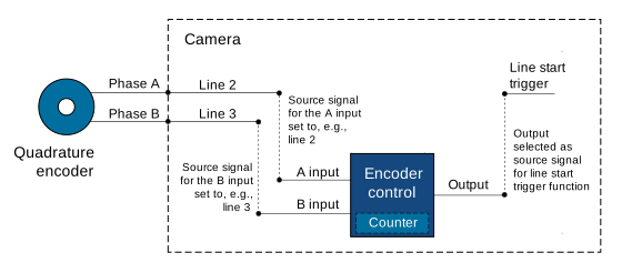
Encoder Control은 두 개의 출력 신호 A와 B를 생성하는 로터리 또는 리니어 방식의 직교 엔코더에 연결됩니다. 이 신호들은 위상 또는 소스 A 및 B라고도 부릅니다. 두 신호는 엔코더의 전진 및 후진 방향 움직임을 추적하는 데 사용되는 90°의 위상 차이를 가집니다. 위상 A와 B는 카메라의 엔코더 제어를 위한 입력 신호입니다.
다음 이미지는 엔코더 제어의 일반적인 구현 예를 보여줍니다.
Encoder Direction of Motion#
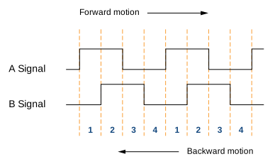
엔코더는 전진 또는 후진 방향으로 움직일 수 있습니다. 움직임 방향을 감지하기 위해 Encoder Control은 A 및 B 신호의 상승 에지와 하강 에지의 순서를 읽습니다.
- 전진 이동 방향: A 신호가 B 신호보다 90° 앞서 상승합니다. 위상 순서는 1-2-3-4입니다.
- 후진 이동 방향: B 신호가 A 신호보다 앞서 상승합니다. 위상 순서는 4-3-2-1입니다.
다음 이미지는 A 및 B 신호의 디지털 신호 레벨에 해당하는 네 가지 위상을 보여줍니다.
Position Counter#
Encoder Control은 A 및 B 신호에 의해 구동되는 position counter를 사용합니다. 카운터 값은 전진 이동 방향에서 증가하고 후진 이동 방향에서 감소합니다.
position counter는 계속해서 작동합니다. 그 값은 마지막 리셋 이후 수신된 들어오는 신호의 수를 나타냅니다. 따라서 카운터 값은 항상 전진 또는 후진 이동 방향과 관련된 대상 개체의 현재 위치를 반영합니다.
Encoder Mode#
엔코더 모드는 들어오는 엔코더 신호가 Encoder Control에 의해 계산되는 방식을 제어합니다.
Four Phase Mode#
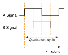
완전히 완료된 네 개의 신호 위상이 하나의 직교 주기를 형성합니다. 완전한 직교 주기마다, 즉 A 신호 에지가 상승할 때 직교 엔코더 카운터가 1만큼 증가하거나 감소합니다.
Four Phase 모드는 매우 안정적이며 두 위상 간의 약간의 신호 지터(jitter)를 필터링할 수 있습니다.
High Resolution Mode#
High Resolution 모드에서는 주기당 카운트가 4배가 됩니다. 엔코더 카운터는 각 신호 위상에서, 즉 A 및 B 신호 에지가 상승 및 하강할 때 1만큼 증가하거나 감소합니다.

정보
High Resolution 모드에서는 지터 필터링이 불가능합니다. 따라서 High Resolution 모드는 다음과 함께 사용하는 것을 권장하지 않습니다. encoder output mode 다음을 다음으로 설정: Motion 두 위상 간의 지터로 인해 연속적인 출력 트리거 펄스가 발생할 수 있기 때문입니다.
Encoder Output Mode#
encoder output mode를 사용하면 Encoder Control이 유효한 출력 신호를 생성하기 위한 조건을 설정할 수 있습니다. 다음과 같은 encoder output mode를 사용할 수 있습니다.
Motion: 이동 방향에 관계없이 출력 트리거 신호가 생성됩니다.DirectionUp: 모든 위치 증가에서 출력 트리거 신호가 생성됩니다. 전진 방향입니다. 역방향 움직임은 무시됩니다.DirectionDown: 모든 위치 증가에서 출력 트리거 신호가 생성됩니다. 역방향 방향입니다. 정방향 움직임은 무시됩니다.PositionUp: 모든 위치에서 출력 트리거 신호가 생성됩니다. new 방향의 전진 위치입니다. 엔코더가 역회전하는 경우, 역회전이 시작된 위치를 다시 통과할 때까지 출력 트리거 신호가 생성되지 않습니다.PositionDown: 모든 위치에서 출력 트리거 신호가 생성됩니다. new 방향의 역방향 위치입니다. 엔코더가 역회전하는 경우, 역회전이 시작된 위치를 다시 통과할 때까지 출력 트리거 신호가 생성되지 않습니다.Off: 출력 트리거 신호가 생성되지 않습니다.
추가 파라미터#
EncoderDivider: 엔코더 출력 트리거 신호를 생성하는 데 필요한 엔코더 입력 신호의 수를 결정합니다.EncoderValue: Position Counter의 현재 값을 가져옵니다. 이 파라미터는 읽기 전용입니다.EncoderReset: Position Counter의 현재 카운터 값을 0으로 재설정합니다. 이 작업은 또한 전체 Encoder Control을 재설정하고 다시 시작합니다. 재시작 직후부터 신호 펄스가 카운트됩니다.
Encoder Control 구성#
Encoder Control을 구성하려면:
- 파라미터를 원하는
EncoderSelector파라메터Encoder1. - 파라미터를 원하는
EncoderSourceAparameter를 사용 가능한 소스 신호 중 하나로 설정합니다(예:Line2. - 파라미터를 원하는
EncoderSourceBparameter를 사용 가능한 소스 신호 중 하나로 설정합니다(예:Line3. - 파라미터를 원하는
EncoderMode파라미터를 설정하십시오: - 파라미터를 원하는
EncoderDivider파라미터를원하는입력신호수로설정합니다. - 파라미터를 원하는
EncoderOutputMode파라미터를 원하는 output mode (으)로 설정합니다(예: 활성화하려는 경우).Motion.
엔코더 신호에 의해 카메라가 트리거되도록 구성하려면:
- 파라미터를 원하는
TriggerSelector파라메터LineStart. - 파라미터를 원하는
TriggerMode파라메터On. - 파라미터를 원하는
TriggerSource파라메터Encoder1.
샘플 코드#
// Select the desired encoder selector
camera.EncoderSelector.SetValue(EncoderSelector_Encoder1)
// Select line 2 as the source signal for the A input of the encoder control
camera.EncoderSourceA.SetValue(EncoderSourceA_Line2);
// Select line 3 as the source signal for the B input of the encoder control
camera.EncoderSourceB.SetValue(EncoderSourceB_Line3);
// Select the desired encoder mode
camera.EncoderMode.SetValue(EncoderMode_FourPhase);
// Determine the number of input signals needed to generate an encoder output trigger signal
camera.EncoderDivider.SetValue(1);
// Select the desired encoder output mode
camera.EncoderOutputMode.SetValue(EncoderOutputMode_Motion);
INodeMap& nodemap = camera.GetNodeMap();
// Select the desired encoder selector
CEnumParameter(nodemap, "EncoderSelector").SetValue("Encoder1");
// Select line 2 as the source signal for the A input of the encoder control
CEnumParameter(nodemap, "EncoderSourceA").SetValue("Line2");
// Select line 3 as the source signal for the B input of the encoder control
CEnumParameter(nodemap, "EncoderSourceB").SetValue("Line3");
// Select the desired encoder mode
CEnumParameter(nodemap, "EncoderMode").SetValue("FourPhase");
// Determine the number of input signals needed to generate an encoder output trigger signal
CIntegerParameter(nodemap, "EncoderDivider").SetValue(1);
// Select the desired encoder output mode
CEnumParameter(nodemap, "EncoderOutputMode").SetValue("Motion");
// Select the desired encoder selector
camera.Parameters[PLCamera.EncoderSelector].SetValue(PLCamera.EncoderSelector.Encoder1);
// Select line 2 as the source signal for the A input of the encoder control
camera.Parameters[PLCamera.EncoderSourceA].SetValue(PLCamera.EncoderSourceA.Line2);
// Select line 3 as the source signal for the B input of the encoder control
camera.Parameters[PLCamera.EncoderSourceB].SetValue(PLCamera.EncoderSourceB.Line3);
// Select the desired encoder mode
camera.Parameters[PLCamera.EncoderMode].SetValue(PLCamera.EncoderMode.FourPhase);
// Determine the number of input signals needed to generate an encoder output trigger signal
camera.Parameters[PLCamera.EncoderDivider].SetValue(1);
// Select the desired encoder output mode
camera.Parameters[PLCamera.EncoderOutputMode].SetValue(PLCamera.EncoderOutputMode.Motion);
/* Macro to check for errors */
#define CHECK(errc) if (GENAPI_E_OK != errc) printErrorAndExit(errc)
GENAPIC_RESULT errRes = GENAPI_E_OK;  /* Return value of pylon methods */
/* Select the desired encoder selector */
errRes = PylonDeviceFeatureFromString(hdev, "EncoderSelector", "Encoder1");
CHECK(errRes);
/* Select line 2 as the source signal for the A input of the encoder control */
errRes = PylonDeviceFeatureFromString(hdev, "EncoderSourceA", "Line2");
CHECK(errRes);
/* Select line 3 as the source signal for the B input of the encoder control */
errRes = PylonDeviceFeatureFromString(hdev, "EncoderSourceB", "Line3");
CHECK(errRes);
/* Select the desired encoder mode */
errRes = PylonDeviceFeatureFromString(hdev, "EncoderMode", "FourPhase");
CHECK(errRes);
/* Determine the number of input signals needed to generate an encoder output trigger signal */
errRes = PylonDeviceSetIntegerFeature(hdev, "EncoderDivider", 1);
CHECK(errRes);
/* Select the desired encoder output mode */
errRes = PylonDeviceFeatureFromString(hdev, "EncoderOutputMode", "Motion");
CHECK(errRes);
# Select the desired encoder selector
camera.EncoderSelector.Value = "Encoder1"
# Select line 2 as the source signal for the A input of the encoder control
camera.EncoderSourceA.Value = "Line2"
# Select line 3 as the source signal for the B input of the encoder control
camera.EncoderSourceB.Value = "Line3"
# Select the desired encoder mode
camera.EncoderMode.Value = "FourPhase"
# Determine the number of input signals needed to generate an encoder output trigger signal
camera.EncoderDivider.Value = 1
# Select the desired encoder output mode
camera.EncoderOutputMode.Value = "Motion"
pylon Viewer를 사용하여 파라미터를 손쉽게 설정할 수도 있습니다.