TDI (Time Delay Integration)#
TDI는 광 민감도를 높이고 더 넓은 다이내믹 레인지를 가진 더 밝은 이미지를 생성하므로 조도가 낮은 환경에서 사용하기에 이상적입니다.
정보
이 기능은 Basler racer 2 XL 및 racer 2 L mono 카메라에서만 지원됩니다.
기능 사용#
이 기능의 구현 방식은 카메라에 따라 다릅니다:
racer 2 XL 카메라#
racer 2 XL 카메라에는 TDI 센서가 탑재되어 있습니다. TDI 센서는 스테이지(stages)라고 하는 여러 행의 픽셀이 배열(array) 형태로 구성되어 있습니다.
피사체가 센서의 시야(Field of View)를 가로질러 이동하면, 첫 번째 스테이지의 노출 영역에서 마지막 스테이지의 노출 영역으로 이미지가 투영됩니다. 스테이지들은 개별적으로 순차 노출되는 것이 아니라 전체 블록으로 노출됩니다. 따라서 센서는 모든 스테이지에서 동일한 피사체를 노출하고, 전하가 리드아웃 라인에 도달할 때까지 전하를 축적 및 전송합니다.
다음 그림은 4개의 스테이지가 있는 센서 내의 전하 전송을 시각화한 것입니다.
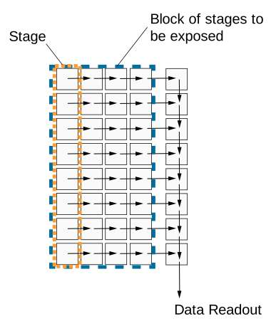
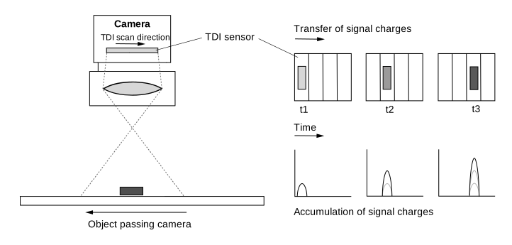
한 스테이지에서 다음 스테이지로의 전하 전송은 피사체의 움직임과 정확히 동기화되어야 합니다. 이를 통해 연속적인 노출과 전하 통합이 보장됩니다. 피사체의 노출은 카메라의 시야 내에 있는 동안 지속됩니다. 스테이지를 많이 사용할수록 유효 Exposure Time 및 통합 시간이 길어집니다.
다음 그림은 TDI 센서의 시야와 전하 이동 원리를 보여줍니다.
Number Of Stages#
스테이지 수는 마지막 스테이지에 도달할 때까지 전하가 축적되고 한 스테이지에서 다음 스테이지로 이동하는 횟수를 결정합니다. 스테이지 수가 많을수록 이미지 감도가 높아집니다. 예를 들어 스테이지 수가 256개인 경우, 카메라는 256배 더 높은 감도로 이미지를 획득합니다. 스테이지 수는 결과적인 Exposure Time에도 영향을 줍니다.
센서는 예를 들어 4개 또는 최대 256개 등 다양한 수의 스테이지로 작동하도록 설정할 수 있습니다. 사용 가능한 스테이지 수는 사용되는 센서에 따라 다릅니다.
스테이지 수를 설정하려면, BslTDINumberOfStages 파라미터 값을 예를 들어 다음과 같이 설정합니다. Stages4 또는 Stages256.
정보
Area sensor acquisition mode에서 스테이지 수는 이미지 높이를 결정합니다. 예를 들어 스테이지 수가 128개로 설정된 경우, r2T16416-500cm 카메라는 Area sensor acquisition mode에서 16416 x 128 "영역" 이미지를 획득합니다.
Scan Direction#
TDI 센서의 스캔 방향은 카메라를 지나는 피사체의 움직임과 동기화되어야 합니다. 연속적인 노출과 전하 통합을 보장하려면 스캔 방향이 피사체의 이동 방향과 같아야 합니다.
정보
스캔 방향 설정 방법에 대한 설명은 카메라에 렌즈를 사용하는 것을 가정합니다. 렌즈는 이미지를 반전시킵니다.
스캔 방향을 설정하려면, BslTDIScanDirection 파라미터를 설정하십시오:
Forward: 센서의 시야를 지나는 피사체는 다음 방향으로 스캔됩니다. 전진 스캔 방향. 피사체는 카메라의 하단을 먼저 지난 후 상단을 지나게 됩니다.Reverse: 센서의 시야를 지나는 피사체는 다음 방향으로 스캔됩니다. 역방향 스캔 방향. 피사체는 카메라의 상단을 먼저 지난 후 하단을 지나게 됩니다.
Resulting Exposure Time#
TDI에서는 센서 수집 모드노출 시간이 ExposureTime 매개변수를 통해 설정되지 않습니다. 대신 다음과 같은 두 가지 취득 매개변수에 의해 결정됩니다.
- Number of stages: 전하가 축적되고 이동하는 동안 물체가 센서의 시야(Field of View)에 머무는 시간을 정의합니다.
- Line rate: 한 단계에서 다음 단계로 전하가 이동하는 속도를 정의합니다. 또한 개별 단계별 적분 시간도 결정합니다.
이 두 매개변수가 결합하여 전체 노출 시간을 결정합니다.
$$ \text{Exposure time} = \frac{\text{Number of stages}}{\text{Line rate}} $$
다음 표는 500 kHz의 고정 Line rate와 다양한 Number of stages에서의 노출 시간 예시를 보여줍니다.
| Number of Stages | Line Rate [kHz] | Exposure Time [µs] |
|---|---|---|
| 4 | 500 | 8 |
| 64 | 500 | 128 |
| 128 | 500 | 256 |
| 256 | 500 | 512 |
다음 표는 128개의 고정된 Number of stages와 최대 500 kHz까지의 다양한 Line rate에서의 노출 시간 예시를 보여줍니다.
| Line Rate [kHz] | Number of Stages | Exposure Time [µs] |
|---|---|---|
| 100 | 128 | 1280 |
| 200 | 128 | 640 |
| 400 | 128 | 320 |
| 500 | 128 | 256 |
Number of stages와 Line rate는 모두 노출 시간에 영향을 미치므로, 트리거링이 물체의 움직임과 올바르게 동기화되어 있고 픽셀 포화 한계가 준수되는 한 이미지 밝기에도 영향을 줍니다.
- Number of stages가 높을수록 노출 시간이 길어져 더 많은 전하가 축적됩니다. 이미지가 더 밝게 나타납니다.
- Number of stages가 낮을수록 노출 시간이 짧아져 적은 전하가 축적됩니다. 이미지가 더 어둡게 나타납니다.
- Line rate가 높을수록 단계별 노출 시간이 짧아져 적은 전하가 축적됩니다. 이미지가 더 어둡게 나타납니다.
- Line rate가 낮을수록 단계별 노출 시간이 길어져 더 많은 전하가 축적됩니다. 이미지가 더 밝게 나타납니다.
TDI용 racer 2 XL 카메라 구성#
TDI용 racer 2 XL 카메라를 구성하려면:
- 파라미터를 원하는
BslSensorAcquisitionMode파라메터TDISingleLine. 센서는 하나의 독출 라인을 사용합니다. - 시스템 설정에 따라
BslTDIScanDirection매개변수를 예시로 설정합니다.Forward. - 파라미터를 원하는
BslTDINumberOfStages매개변수를 예를 들어 128로 설정합니다.
정보
- 센서의 독출 절차가 물체의 이동 속도 및 방향과 정확히 동기화되도록 하십시오. 테스트를 위해 Acquisition Line Rate를 그에 맞게 변경하십시오. 이는 결과적인 Exposure Time에도 영향을 미칩니다.
- 트리거 일시 중지 후 다시 트리거할 때는 최소한 첫 번째 n개의 독출 라인을 유효하지 않은 것으로 간주해야 하며, 여기서 n은 최소 Number of stages를 나타냅니다.
racer 2 L 흑백 카메라#
racer 2 L mono cameras는 다중 라인 센서, 즉 듀얼 라인 또는 쿼드 라인 센서가 장착되어 있습니다. 센서의 각 픽셀 라인은 서로 다른 Exposure Time으로 노출되도록 설정할 수 있습니다. 취득이 트리거될 때마다 센서의 모든 픽셀 라인이 동시에 노출됩니다. 단일 노출의 경우, 카메라를 통과하는 물체에 대해 각 라인의 시야가 다르기 때문에 센서의 각 라인은 물체의 서로 다른 영역을 취득합니다.
다음 그림은 모노 쿼드 라인 센서의 시야(Field of View)를 보여줍니다.
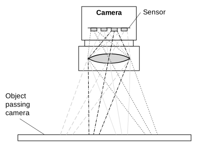
이 경우, 오브젝트의 특정 영역에 대한 전체 정보를 얻으려면 네 번의 서로 다른 획득 데이터를 버퍼링하고 결합해야 합니다. 이는 Spatial Correction을 통해 수행됩니다. 현재 노출의 마지막 라인 데이터는 과거 노출에서 가져온 이전 라인 데이터와 결합됩니다.
Line Combination Mode를 사용하여 HDR 이미지를 얻기 위해 개별 라인의 픽셀 값을 결합하는 방식을 최종적으로 지정할 수 있습니다.
Line Combination Mode#
라인 조합 모드를 사용하면 결합된 센서 라인의 픽셀 값을 합산할지 또는 평균화할지 정의할 수 있습니다. 다음을 설정할 수 있습니다. BslLineCombinationMode 파라미터를 설정하십시오:
Off: 라인 조합이 비활성화됩니다.TDISum: 결합된 센서 라인의 픽셀 값이 합산됩니다. 이는 카메라의 광 감도와 신호 대 잡음비를 증가시킵니다.TDIAverage: 결합된 센서 라인의 픽셀 값이 평균화됩니다. 이는 카메라의 광 감도에 영향을 주지 않고 신호 대 잡음비를 증가시킵니다.
TDI용 racer 2 L Mono 카메라 구성#
TDI용 racer 2 L 모노 카메라를 구성하려면:
- 파라미터를 원하는 센서 수집 모드 듀얼 또는 쿼드 라인 이미지 획득으로 설정:
파라미터를 원하는BslSensorAcquisitionMode파라메터DualLine또는QuadLineTDI에 두 개 또는 네 개의 라인 중 어느 것을 사용할지에 따라 다릅니다. -
각 라인(스테이지)의 Exposure Time을 지정합니다:
- 파라미터를 원하는
ExposureTimeMode파라메터Individual. - 파라미터를 원하는
ExposureTimeSelector파라메터Stage1. - 파라미터를 원하는
ExposureTime파라미터를 원하는 Exposure Time(마이크로초 단위)으로 설정합니다.
참고: 카메라 모델의 최소 및 최대 Exposure Time 값은 다음에서 확인할 수 있습니다: 세부 정보 섹션 Exposure Time 항목입니다. - 다른 스테이지에 대해서도 단계 b와 c를 반복합니다.
- 파라미터를 원하는
-
지정: Spatial Correction 스트라이드 Spatial Correction의 시작 라인과 방향을 결정하려면:
파라미터를 원하는BslSpatialCorrectionStride파라미터를 예를 들어 2로 설정합니다. - 파라미터를 원하는 Line Combination Mode 결합된 라인의 센서 픽셀 값을 합산할지 평균화할지 결정하려면:
파라미터를 원하는BslLineCombinationMode매개변수를 예시로 설정합니다.TDIAverage.
외부 후처리 프로그램을 사용하여 라인 정보를 결합하고 하이 다이나믹 레인지 이미지를 생성합니다.
샘플 코드#
racer 2 XL 카메라#
// Set the sensor acquisition mode to TDI Single Line
camera.BslSensorAcquisitionMode.SetValue(BslSensorAcquisitionMode_TDISingleLine);
// Set the sensor scan direction to Forward
camera.BslTDIScanDirection.SetValue(BslTDIScanDirection_Forward);
// Set the number of stages to 128
camera.BslTDINumberOfStages.SetValue(BslTDINumberOfStages_128);
INodeMap& nodemap = camera.GetNodeMap();
// Set the sensor acquisition mode to TDI Single Line
CEnumParameter(nodemap, "BslSensorAcquisitionMode").SetValue("TDISingleLine");
// Set the sensor scan direction to Forward
CEnumParameter(nodemap, "BslTDIScanDirection").SetValue("Forward");
// Set the number of stages to 128
CEnumParameter(nodemap, "BslTDINumberOfStages").SetValue("");
// Set the sensor acquisition mode to TDI Single Line
camera.Parameters[PLCamera.BslSensorAcquisitionMode].SetValue(PLCamera.BslSensorAcquisitionMode.TDISingleLine);
// Set the sensor scan direction to Forward
camera.Parameters[PLCamera.BslTDIScanDirection].SetValue(PLCamera.BslTDIScanDirection.Forward);
// Set the number of stages to 128
camera.Parameters[PLCamera.BslTDINumberOfStages].SetValue(PLCamera.BslTDINumberOfStages.);
/* Macro to check for errors */
#define CHECK(errc) if (GENAPI_E_OK != errc) printErrorAndExit(errc)
GENAPIC_RESULT errRes = GENAPI_E_OK;  /* Return value of pylon methods */
/* Set the sensor acquisition mode to TDI Single Line */
errRes = PylonDeviceFeatureFromString(hdev, "BslSensorAcquisitionMode", "TDISingleLine");
CHECK(errRes);
/* Set the sensor scan direction to Forward */
errRes = PylonDeviceFeatureFromString(hdev, "BslTDIScanDirection", "Forward");
CHECK(errRes);
/* Set the number of stages to 128 */
errRes = PylonDeviceFeatureFromString(hdev, "BslTDINumberOfStages", "");
CHECK(errRes);
racer 2 L 흑백 카메라#
// Set the sensor acquisition mode to Dual Line
camera.BslSensorAcquisitionMode.SetValue(BslSensorAcquisitionMode_DualLine);
// Set the exposure time for both lines (stages)
// Select stage 1
camera.ExposureTimeSelector.SetValue(ExposureTimeSelector_Stage1);
// Set the exposure time to 1000 microseconds
camera.ExposureTime.SetValue(1000.0);
// Select stage 2
camera.ExposureTimeSelector.SetValue(ExposureTimeSelector_Stage2);
// Set the exposure time to 1000000 microseconds
camera.ExposureTime.SetValue(1000000.0);
// Set the spatial correction stride to 2
camera.BslSpatialCorrectionStride.SetValue(BslSpatialCorrectionStride_2);
// Set the line combination mode to TDI Sum
camera.BslLineCombinationMode.SetValue(BslLineCombinationMode_TDISum);
INodeMap& nodemap = camera.GetNodeMap();
// Set the sensor acquisition mode to Dual Line
CEnumParameter(nodemap, "BslSensorAcquisitionMode").SetValue("DualLine");
// Set the exposure time for both lines (stages)
// Select stage 1
CEnumParameter(nodemap, "ExposureTimeSelector").SetValue("Stage1");
// Set the exposure time to 1000 microseconds
CFloatParameter(nodemap, "ExposureTime").SetValue(1000.0);
// Select stage 2
CEnumParameter(nodemap, "ExposureTimeSelector").SetValue("Stage2");
// Set the exposure time to 1000000 microseconds
CFloatParameter(nodemap, "ExposureTime").SetValue(1000000.0);
// Set the spatial correction stride to 2
CEnumParameter(nodemap, "BslSpatialCorrectionStride").SetValue("");
// Set the line combination mode to TDI Sum
CEnumParameter(nodemap, "BslLineCombinationMode").SetValue("TDISum");
// Set the sensor acquisition mode to Dual Line
camera.Parameters[PLCamera.BslSensorAcquisitionMode].SetValue(PLCamera.BslSensorAcquisitionMode.DualLine);
// Set the exposure time for both lines (stages)
// Select stage 1
camera.Parameters[PLCamera.ExposureTimeSelector].SetValue(PLCamera.ExposureTimeSelector.Stage1);
// Set the exposure time to 1000 microseconds
camera.Parameters[PLCamera.ExposureTime].SetValue(1000.0);
// Select stage 2
camera.Parameters[PLCamera.ExposureTimeSelector].SetValue(PLCamera.ExposureTimeSelector.Stage2);
// Set the exposure time to 1000000 microseconds
camera.Parameters[PLCamera.ExposureTime].SetValue(1000000.0);
// Set the spatial correction stride to 2
camera.Parameters[PLCamera.BslSpatialCorrectionStride].SetValue(PLCamera.BslSpatialCorrectionStride.);
// Set the line combination mode to TDI Sum
camera.Parameters[PLCamera.BslLineCombinationMode].SetValue(PLCamera.BslLineCombinationMode.TDISum);
/* Macro to check for errors */
#define CHECK(errc) if (GENAPI_E_OK != errc) printErrorAndExit(errc)
GENAPIC_RESULT errRes = GENAPI_E_OK;  /* Return value of pylon methods */
/* Set the sensor acquisition mode to Dual Line */
errRes = PylonDeviceFeatureFromString(hdev, "BslSensorAcquisitionMode", "DualLine");
CHECK(errRes);
/* Set the exposure time for both lines (stages) */
/* Select stage 1 */
errRes = PylonDeviceFeatureFromString(hdev, "ExposureTimeSelector", "Stage1");
CHECK(errRes);
/* Set the exposure time to 1000 microseconds */
errRes = PylonDeviceSetFloatFeature(hdev, "ExposureTime", 1000.0);
CHECK(errRes);
/* Select stage 2 */
errRes = PylonDeviceFeatureFromString(hdev, "ExposureTimeSelector", "Stage2");
CHECK(errRes);
/* Set the exposure time to 1000000 microseconds */
errRes = PylonDeviceSetFloatFeature(hdev, "ExposureTime", 1000000.0);
CHECK(errRes);
/* Set the spatial correction stride to 2 */
errRes = PylonDeviceFeatureFromString(hdev, "BslSpatialCorrectionStride", "");
CHECK(errRes);
/* Set the line combination mode to TDI Sum */
errRes = PylonDeviceFeatureFromString(hdev, "BslLineCombinationMode", "TDISum");
CHECK(errRes);
# Set the sensor acquisition mode to Dual Line
camera.BslSensorAcquisitionMode.Value = "DualLine"
# Set the exposure time for both lines (stages)
# Select stage 1
camera.ExposureTimeSelector.Value = "Stage1"
# Set the exposure time to 1000 microseconds
camera.ExposureTime.Value = 1000.0
# Select stage 2
camera.ExposureTimeSelector.Value = "Stage2"
# Set the exposure time to 1000000 microseconds
camera.ExposureTime.Value = 1000000.0
# Set the spatial correction stride to 2
camera.BslSpatialCorrectionStride.Value = ""
# Set the line combination mode to TDI Sum
camera.BslLineCombinationMode.Value = "TDISum"
pylon Viewer를 사용하여 파라미터를 손쉽게 설정할 수도 있습니다.