
Operator Library: Hardware Platform
The GPI operator provides an interface to the digital inputs. Via the Pin_ID / PinID parameter (the name of the parameter depends on the hardware platform), you select the digital input (which is wired to a physical pin on a GPIO unit) you want to use for receiving a signal. The same digital inputs can be used by multiple operators.
For all platforms except the imaFlex platforms: If you use a device with several GPIO units, use the ConnectorType parameter to select the GPIO unit you want to address (Front GPIO or GPIO). On the imaFlex 2 Dual 100, imaFlex CXP-12 Quad and imaFlex CXP-12 Penta platforms, the parameter ConnectorType is not available.
![[참고]](../common/images/admon/note.png) |
Front GPI Port Groups and Signal Modes on the imaFlex 2 Dual 100 Platform |
|---|---|
|
The front GPI ports on the imaFlex 2 Dual 100 platform are divided into two independent groups:
The AppletProperties operator controls whether a front GPI port group operates in single-ended or differential mode. If the FrontGpiPullControl03 / FrontGpiPullControl47 parameter on the AppletProperties operator is set to Differential:
Example: If the FrontGpiType03 parameter is set to Differential in the AppletProperties operator, and the design requires a differential signal on ports 0 and 1:
|
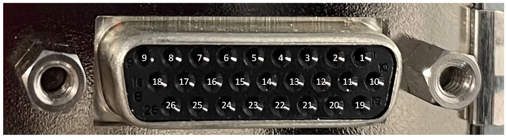
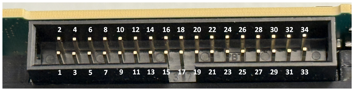
For the mapping of digital inputs and pin connectors, see the GPIO Connectors topic of your frame grabber User Manual. For the imaFlex 2 Dual 100 plaform, see GPIO Connectors (CoF Frame Grabbers).
| 하드웨어 플랫폼별 지원 여부 |
|---|
| imaFlex 2 Dual 100 |
| imaFlex CXP-12 Penta |
| imaFlex CXP-12 Quad |
| mE5 marathon VCLx |
| mE5 marathon VCL |
| mE5 marathon VCX-QP |
| mE5 marathon VF2 |
| LightBridge VCL |
| mE5 ironman VQ8-CXP6D/-CXP6B |
| mE5 ironman VD8-PoCL |
| pixelPlant 100 |
| pixelPlant 200 |
리소스
The FPGA device resources of this operator are equal to value of the PinID / Pin_ID parameter. You can see the FPGA device resources, if you open the dialog from the menu. The device resources are read-only:
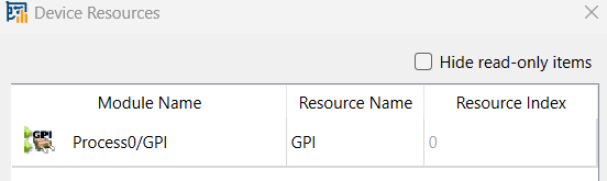
For the imaFlex 2 Dual 100 platform, the resource is of type GPI with index 0 to 7 for Front GPIO connector and 8 to 15 – for the Extension GPIO connector.
| Property | Value |
|---|---|
| Operator Type | M |
| 출력 링크 | O, general purpose input signal to be used inside VisualApplets. |
| Link Parameter | Output Link O |
|---|---|
| Bit Width | 1 |
| Arithmetic | unsigned |
| Parallelism | 1 |
| Kernel Columns | 1 |
| Kernel Rows | 1 |
| Img Protocol | VALT_SIGNAL |
| Color Format | VAF_GRAY |
| Color Flavor | FL_NONE |
| Max. Img Width | any |
| Max. Img Height | any |
| PinID (모든 imaFlex 플랫폼) | |||||||||||||||||||||||||||||||||||||||||||||||||||||||||||||
|---|---|---|---|---|---|---|---|---|---|---|---|---|---|---|---|---|---|---|---|---|---|---|---|---|---|---|---|---|---|---|---|---|---|---|---|---|---|---|---|---|---|---|---|---|---|---|---|---|---|---|---|---|---|---|---|---|---|---|---|---|---|
| Type | 정적 쓰기 파라미터 | ||||||||||||||||||||||||||||||||||||||||||||||||||||||||||||
| Default | FrontGpi0 | ||||||||||||||||||||||||||||||||||||||||||||||||||||||||||||
| Range |
imaFlex CXP-12 Quad and imaFlex CXP-12 Penta: {FrontGpi0, FrontGpi1, FrontGpi2, FrontGpi3, ExtensionGpi0, ExtensionGpi1, ExtensionGpi2, ExtensionGpi3, ExtensionGpi4, ExtensionGpi5, ExtensionGpi6, ExtensionGpi7}; imaFlex 2 Dual 100: {FrontGpi0, FrontGpi1, FrontGpi2, FrontGpi3, FrontGpi4, FrontGpi5, FrontGpi6, FrontGpi7, ExtensionGpi0, ExtensionGpi1, ExtensionGpi2, ExtensionGpi3, ExtensionGpi4, ExtensionGpi5, ExtensionGpi6, ExtensionGpi7} |
||||||||||||||||||||||||||||||||||||||||||||||||||||||||||||
|
Via the PinID parameter, you define the digital input (which is wired to a physical pin on a GPIO socket) you want to use for receiving a signal. The same digital inputs can be used by multiple operators. FrontGpiN represents the GPI for the Front GPIO connector. ExtensionGpiN represents the GPI for Extension GPIO side connector. 디지털 입력과 핀 커넥터 매핑에 대해서는 프레임 그래버 사용자 매뉴얼의 GPIO Connectors 항목을 참조하십시오. imaFlex 2 Dual 100 플랫폼의 경우 GPIO Connectors (CoF Frame Grabbers)를 참조하십시오.
|
|||||||||||||||||||||||||||||||||||||||||||||||||||||||||||||
| Pin_ID (mE5 플랫폼, Pixelplant 및 LightBridge VCL) | ||||
|---|---|---|---|---|
| Type | 정적 쓰기 파라미터 | |||
| Default | 0 | |||
| Range | [0;7] 또는 [0;3] | |||
|
파라미터 Pin_ID를 통해 신호를 수신하는 데 사용할 디지털 입력(GPIO 소켓의 물리적 핀에 연결됨)을 정의합니다. 동일한 디지털 입력을 여러 오퍼레이터가 사용할 수 있습니다. [0;3] 값 범위는 marathon의 Front GPIO, LightBridge의 Front GPIO, 그리고 LightBridge의 GPIO에서 0~3입니다. [0;7] marathon의 GPIO 및 기타 모든 경우에서 값 범위는 0~7입니다.
|
||||
| ConnectorType (mE5 marathon 및 LightBridge VCL 플랫폼) | ||||
|---|---|---|---|---|
| Type | 정적 쓰기 파라미터 | |||
| Default | GPIO | |||
| Range | {FrontGPIO, GPIO} | |||
|
ConnectorType 파라미터를 통해 Pin_ID 파라미터에 입력한 값으로 제어할 GPIO 소켓(GPIO 또는 Front GPIO)을 정의합니다.
|
||||
다음 예시에서 GPI 오퍼레이터의 사용법을 보여 줍니다.
-
DMA, RAM, GPIO, Trigger 및 LED의 하드웨어 자체 테스트 예시.
-
'Area Scan Trigger for microEnable 5 marathon'
영역 스캔 트리거가 제공됩니다. 외부 소스, 내부 주파수 생성기 또는 소프트웨어 트리거 펄스를 트리거 생성에 사용할 수 있습니다.
-
'Area Scan Trigger for microEnable 5 marathon VCX QP'
CoaXPress용 영역 스캔 트리거가 제공됩니다. 외부 소스, 내부 주파수 생성기 또는 소프트웨어 트리거 펄스를 트리거 생성에 사용할 수 있습니다.
-
'Area Scan Trigger for imaFlex CXP-12 Quad'
CoaXPress12용 영역 스캔 트리거가 제공됩니다. 외부 소스, 내부 주파수 생성기 또는 소프트웨어 트리거 펄스를 트리거 생성에 사용할 수 있습니다.
-
'TrgBoxLine 오퍼레이터를 사용하는 microEnable 5 marathon VCL용 라인 스캔 트리거 사용법'
간단한 디자인에서 TrgBoxLine 오퍼레이터의 사용법을 보여주는 VisualApplets 디자인 예시입니다.
-
'Line Scan Trigger for microEnable 5 marathon VCX QP Using Signal Operators'
라인 스캔 트리거가 제공됩니다. 이 트리거에는 캡처 게이트를 사용하는 이미지 트리거와 다기능 라인 트리거가 포함됩니다. 트리거 생성을 위해 외부 소스, 내부 주파수 생성기 또는 소프트웨어 트리거 펄스를 사용할 수 있습니다.
-
'TrgBoxLine 오퍼레이터를 사용하는 microEnable 5 marathon VCX QP용 라인 스캔 트리거 사용법'
간단한 디자인에서 TrgBoxLine 오퍼레이터의 사용법을 보여주는 VisualApplets 디자인 예시입니다.
-
'Line Scan Trigger for imaFlex CXP-12 Quad Using Signal Operators'
CoaXPress12용 라인 스캔 트리거가 제공됩니다. 이 트리거에는 캡처 게이트를 사용하는 이미지 트리거와 다기능 라인 트리거가 포함됩니다. 트리거 생성을 위해 외부 소스, 내부 주파수 생성기 또는 소프트웨어 트리거 펄스를 사용할 수 있습니다.
-
'TrgBoxLine 오퍼레이터를 사용하는 imaFlex CXP-12 Quad용 라인 스캔 트리거 사용법'
간단한 디자인에서 TrgBoxLine 오퍼레이터의 사용법을 보여주는 VisualApplets 디자인 예시입니다.
 이전
이전

